
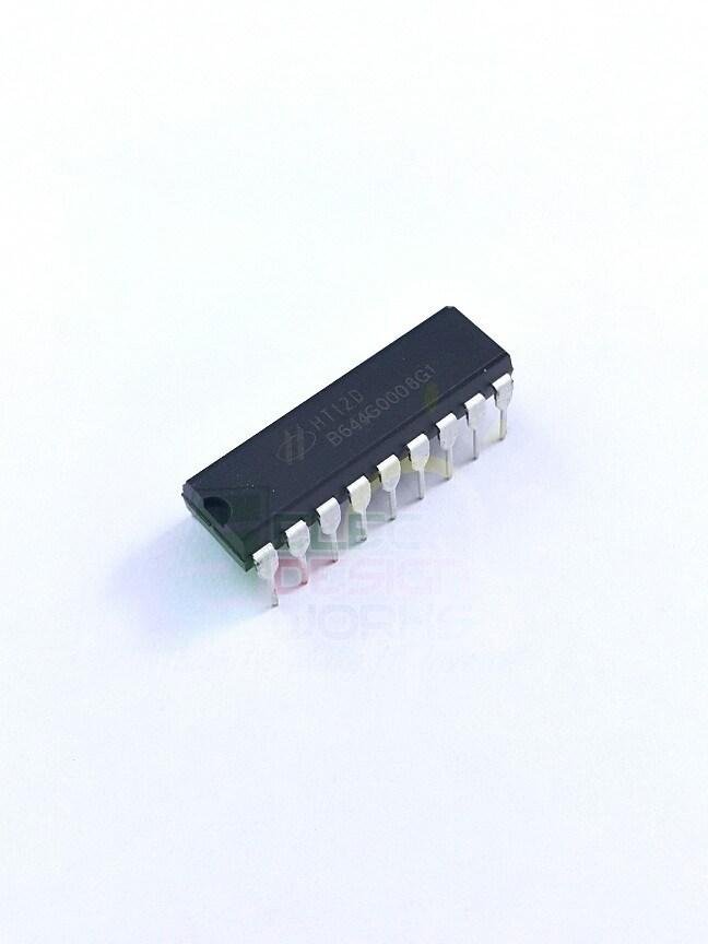
Description
| Pin Number | Pin Name | Description |
| 1 to 8 | A0,A1,A2,A3,A4,A5,A6 & A7 | These are the 8-bit address bits, which is used to protect your data. We should set the bits in same pattern on Encoder and Decoder IC to pair them. |
| 9 | Ground/Vss | Connected to the Ground of circuit |
| 10 to 13 | AD0, AD1, AD2 & AD3 | These four pins are used to obtain the data bits by decoding the data from HT12E IC |
| 14 | Input | The Encoded 12 bit output data obtained from HT12E has to be given here |
| 15 and 16 | Oscillator pins 1 & 2 | The IC has a built in oscillator. This oscillator can be used by connecting these two pins through a 1M Resistor |
| 17 | Valid Transmission (VT) | This pin will go high when a data is received. It is not mandatory to use it. |
| 16 | Vcc/Vdd | This pin powers the IC should use only 5V |
Features
- 12-bit Decoder IC to be used with HT12E
- Decoded data has 4 Data bits and 8 Address bits (8+4=12-bits)
- Commonly used for RF and IR wireless transmission
- Operating Voltage 5V
- Low stand by the current of 0.1uA at Vcc=5V
- Available in 16-pin DIP, 20-pin SOP

Reviews
There are no reviews yet.